Home
Galerie
Kontakt
Jewelry Aesthetic
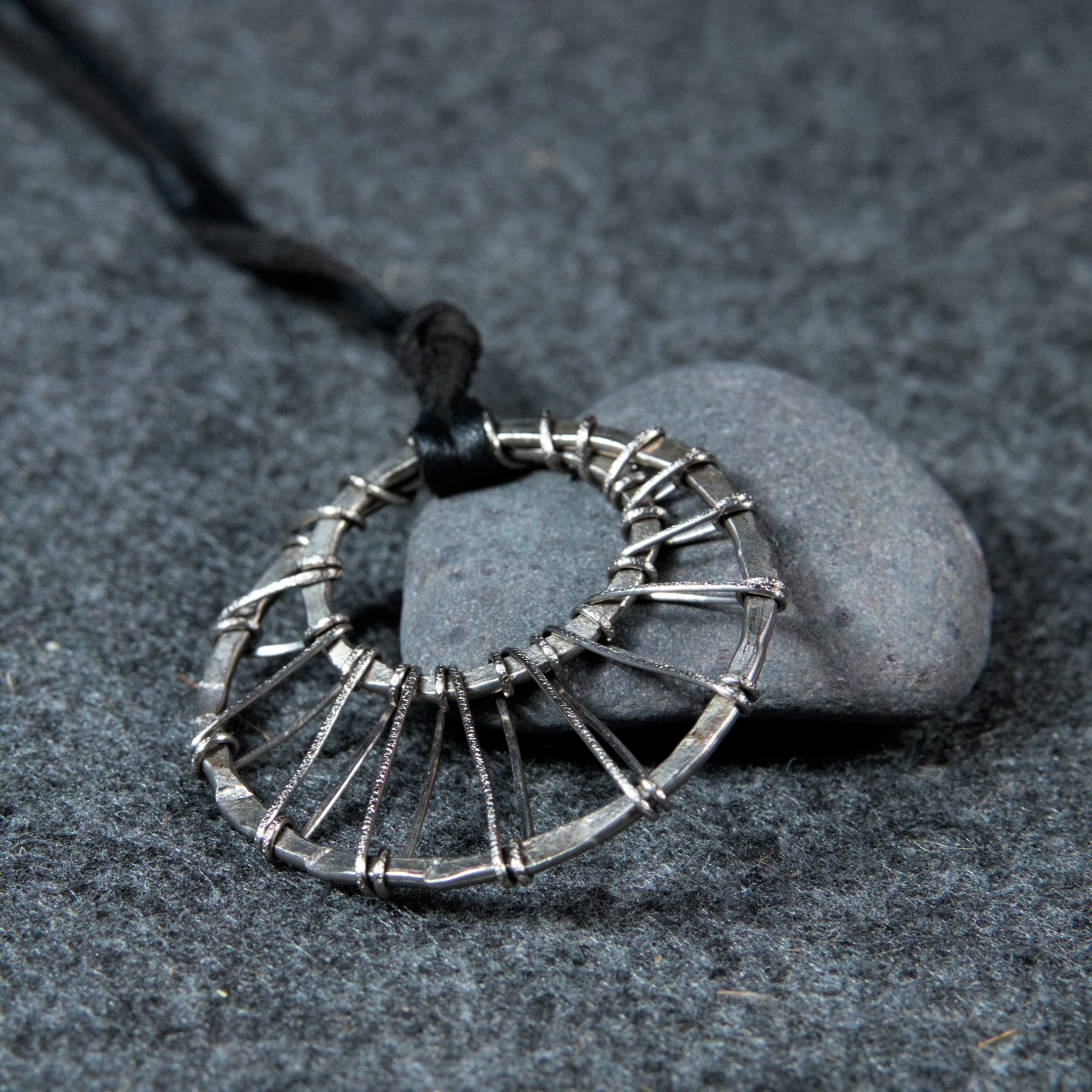
Sun on the Moon
32.90
€
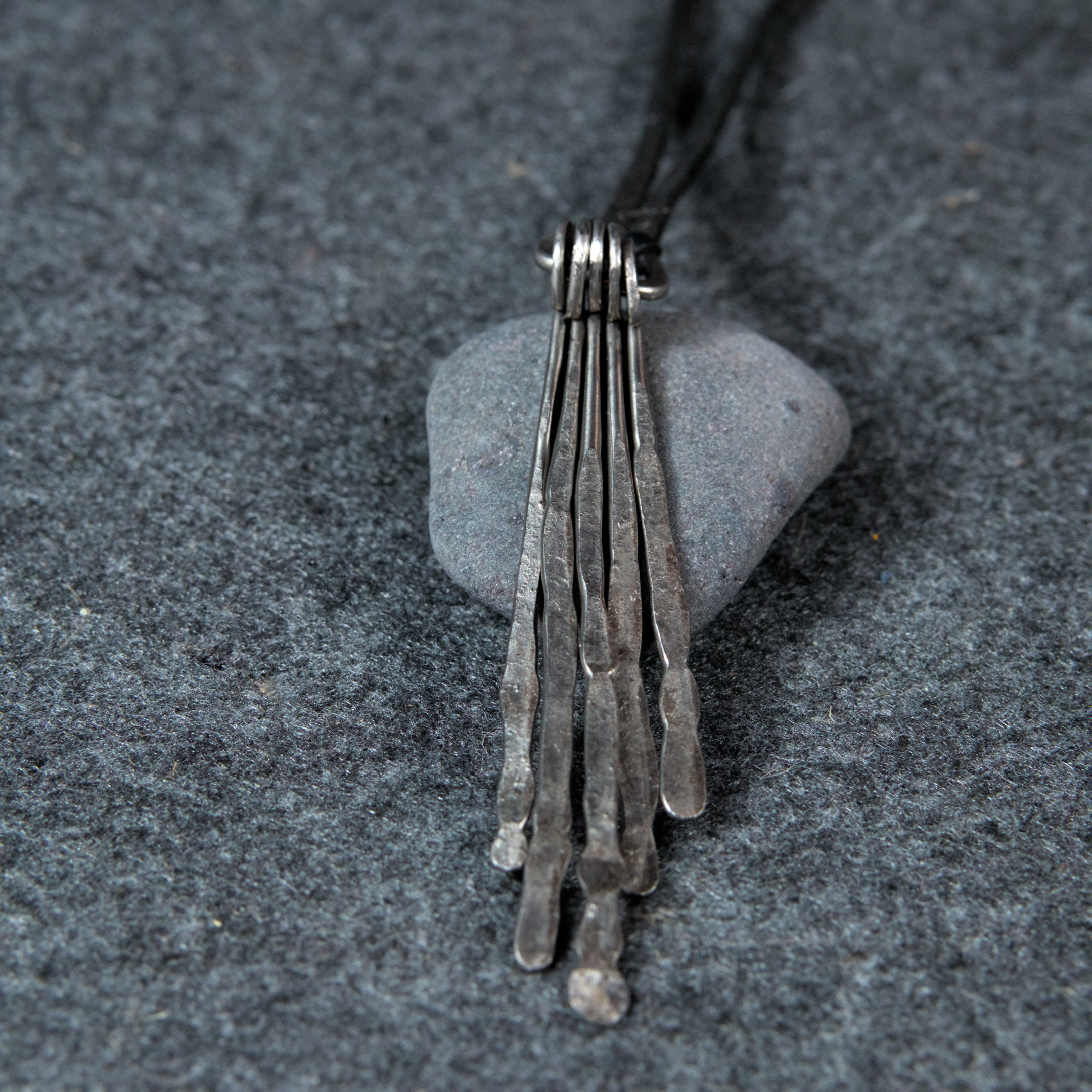
Star Light
16.90
€
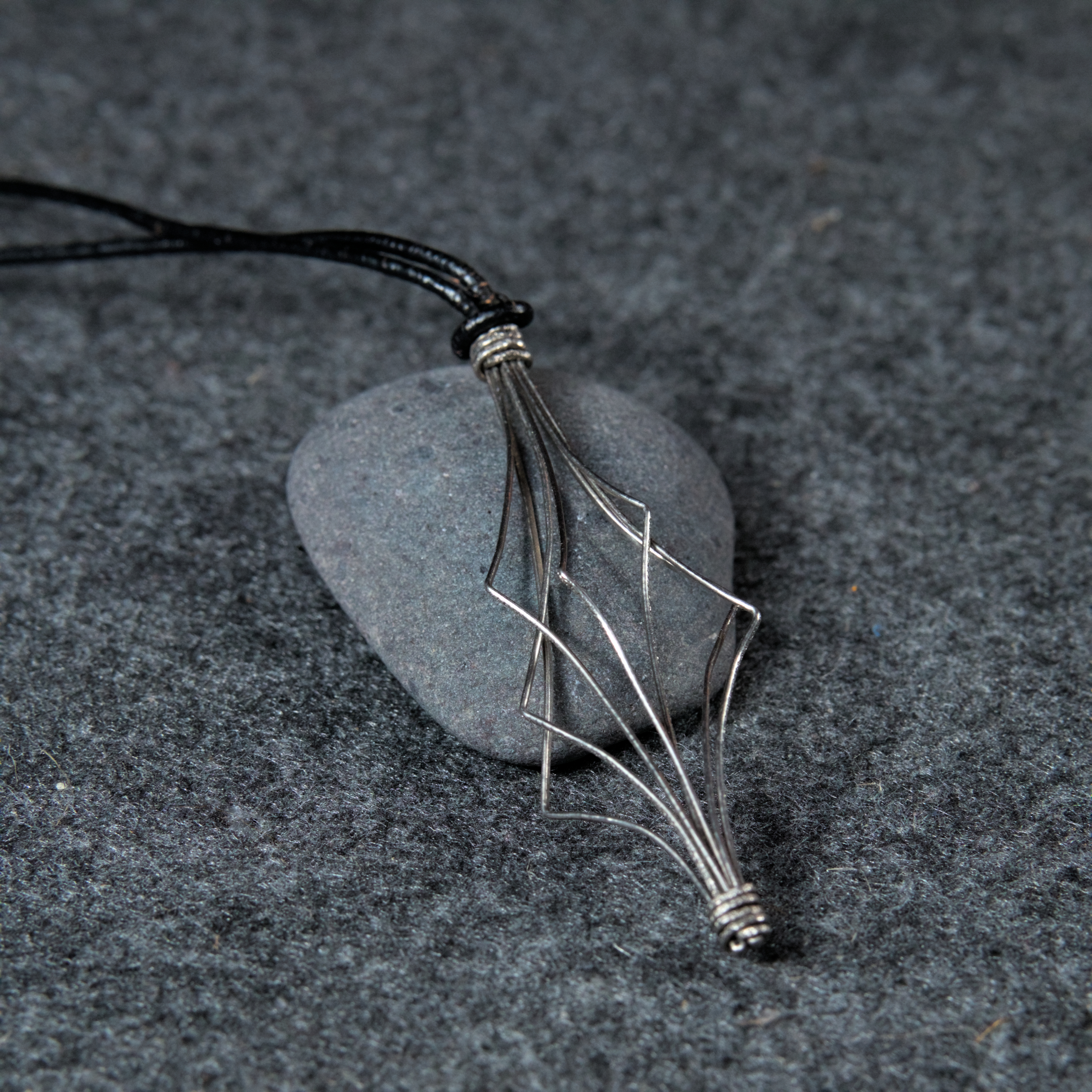
Pentatonica
25.90
€
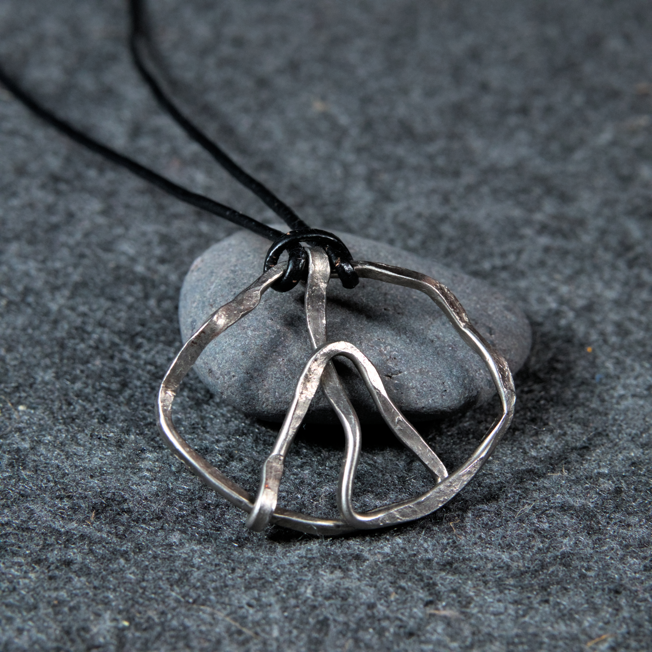
Fragile Peace
19.90
€
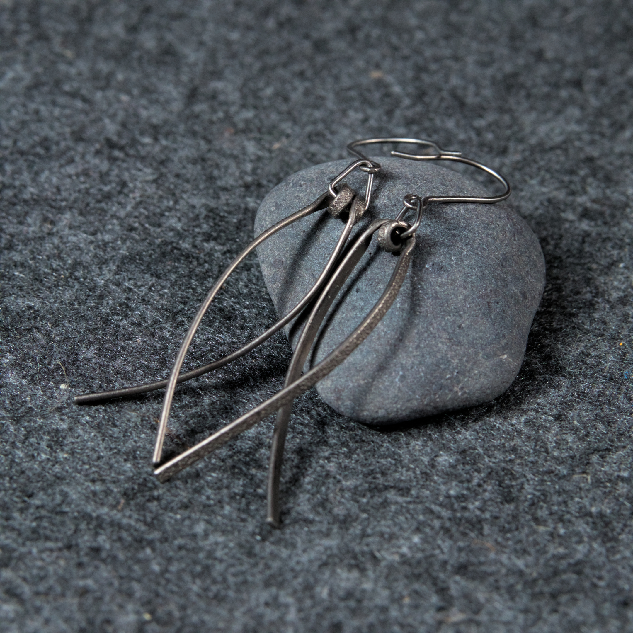
Ohrringe “Heiliger Fisch 0.4”
29.90
€